This is a blog that has been a long time coming. Recently in the shop was a 2007 Lexus ES350 with a a severe timing cover leak. The guest opted to have us replace the headgaskets and VVT intake gears while the drivetrain was out as well. Seeing as our guide to timing the 2GR-FE is one of the most popular we’ve ever published (for good reason, as this engine is tough to time correctly!), we decided to go all in and document as much of the teardown process as possible. Why not the rebuilding? 99% of the rebuild is the reverse of teardown. At the end of the guide we’ve noted a few tips, but by and large reassembly is a straightforward reversal of the below.
Note that some of the pictures aren’t in perfect order and/or are reused.
Disclaimer: this blog post is not intended to be used as a repair guide, and is only to illustrate the process of tearing down the 2GR-FE and it’s quirks. We forgot to take some pictures of some steps as well. This is meant to be light technical read as we love sharing our work. This teardown is not easy and should not be attempted by anyone other than a seasoned Toyota expert with proper tools and equipment. Do not try this at home.
The gas cap is removed before disconnecting the battery.
The vehicle is lifted, the steering wheel locked in place, and the shrouds removed:
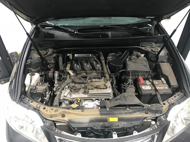
Shroud Removal
The battery is removed:
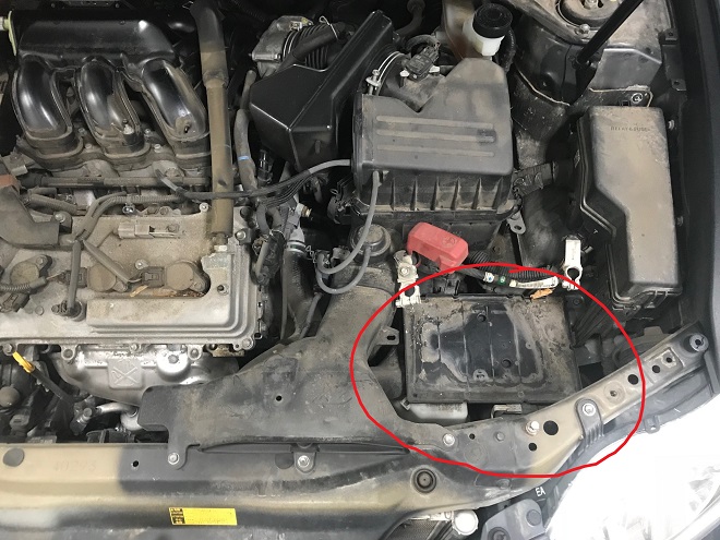
Battery Removal
The negative terminal is disconnected. Wait 10 minutes before you do anything else so any system capacitance can dissipate. The battery tray is removed, as is some intake tubing:
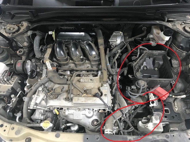
More Airbox Removal
The upper airbox at the throttle body is held on with a 10mm clamp, the box clamped shut with spring clamps, and the fresh air intake by a series of 10mm bolts, clips, etc. The MAF sensor connector, various evaporative emissions hoses, and vacuum feed lines are disconnected. Most of the lines and connectors get moved out of the way for now.
The lower section of the airbox is removed. (No picture of this step, but removed in later photos).
NOT PICTURED: the vacuum feed line from the back of the intake manifold to the brake booster is disconnected.
A few things require removal in the engine junction block:
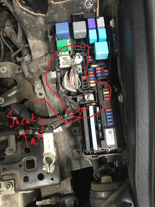
Fuse Block Before
The harness connectors and power feed are disconnected. There is a sneaky tab that holds in part of the harness.
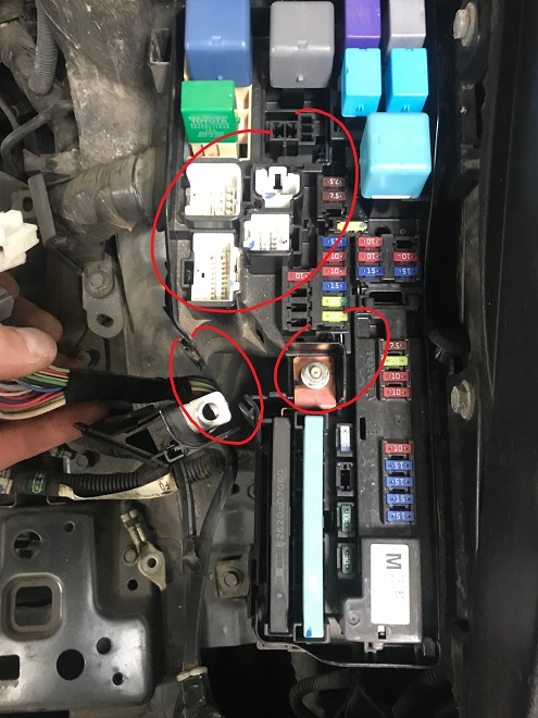
Fuse Block After
The harness from above is moved off to the side, disconnecting ground straps and connector secures as needed to move it near the throttle body. This harness is coming out with the drivetrain. The positive terminal 12mm nut is removed, releasing the cable that runs to the starter. The starter cable is moved to the side of the starter (a few connectors need to be released so the cable is entirely free of the body), the positive terminal off to the side of the engine bay. The starter cable is being removed with the drivetrain (this picture is upside down):
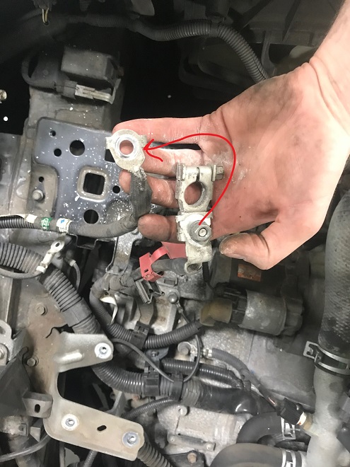
Battery Terminal Separate
The passenger side engine mount is removed:

Remove upper mount
The mount is removed in two parts- a small black piece that connects to the lower intake manifold and the main mount that secures to the body.
The Bank 2 Air/Fuel ratio sensor connector is disconnected from the upper radiator hose:
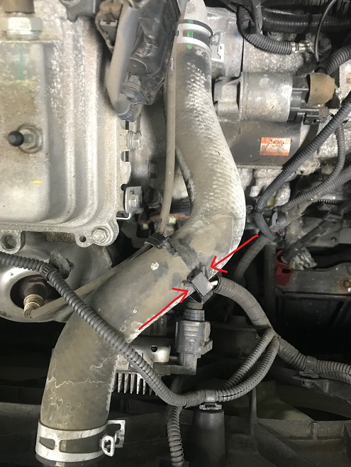
Upper coolant hose disconnect
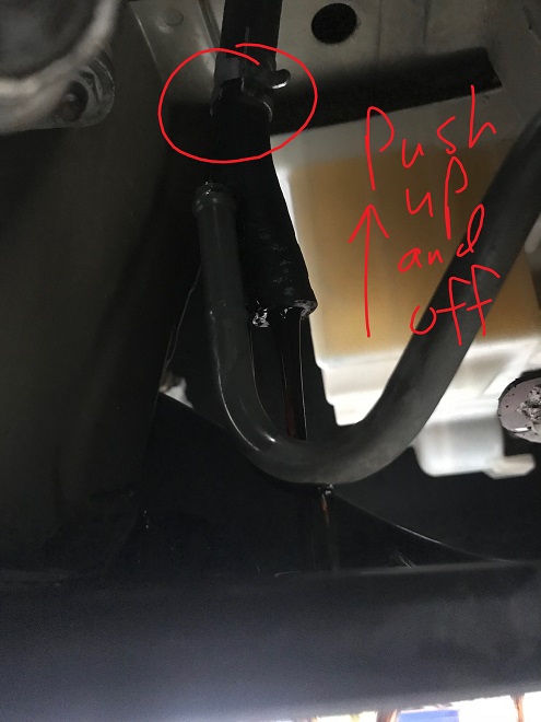
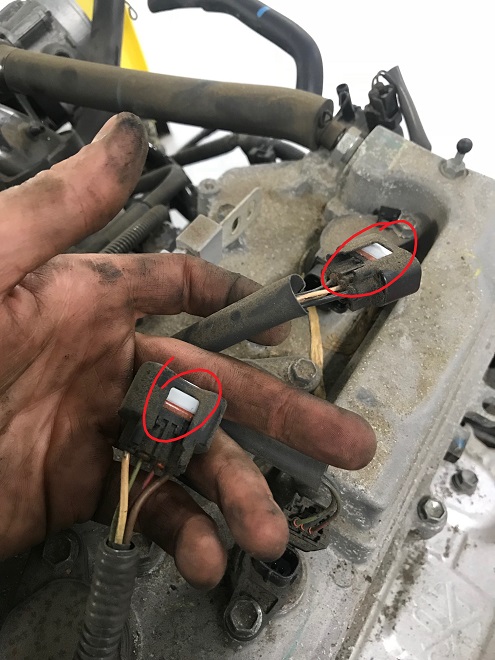
The fuel supply line and transmission shift control cables are disconnected:
Fuel line disconnect
If the transmission cable at the collar and tab that hold it in place can’t be removed due to rust, it can be unbolted from the transmission:
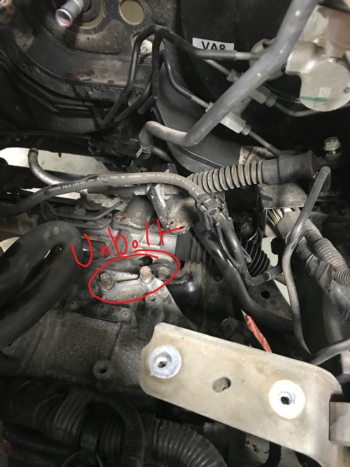
Unbolted transmission line, moved up
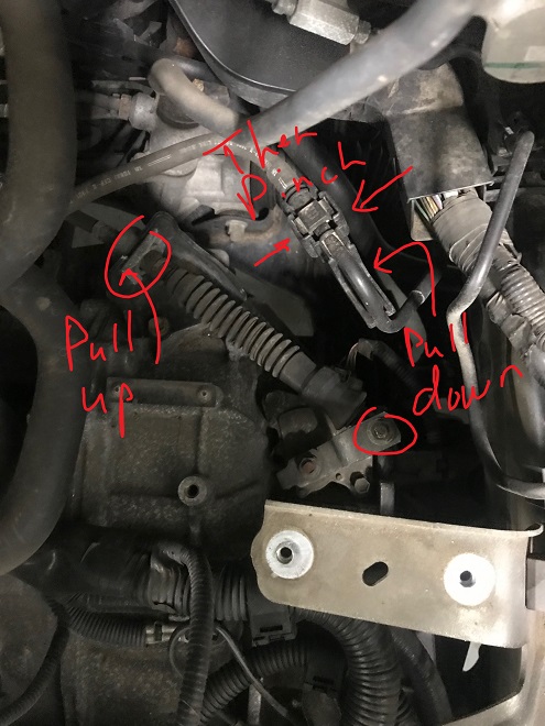
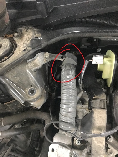
On the fuel line:
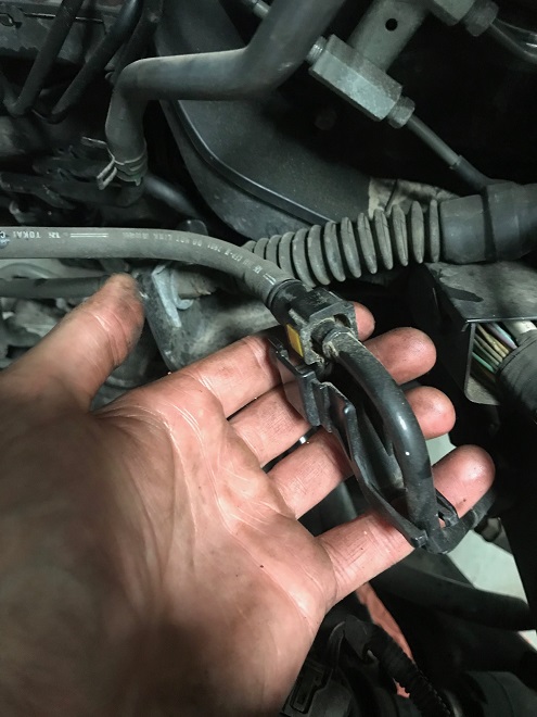
Pull cover down and off
And the line exposed:
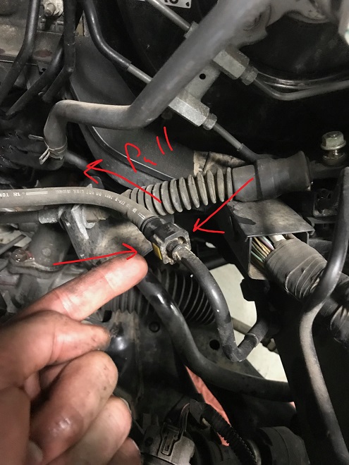
Fuel line connector
The fuel line disconnect cover is removed by pulling downward, then the line squeezed. There will be a small amount of fuel spray when it is disconnected. The exposed fuel line is covered to minimized fuel dripping or pooling. Small amounts of fuel will escape when the lines are moved about. Remember the removed gas cap? Because the fuel line is disconnected, any pressure that builds in the tank will push it’s way out this disconnected line. With the pressure relieved by the cap fuel dripping is minimized.
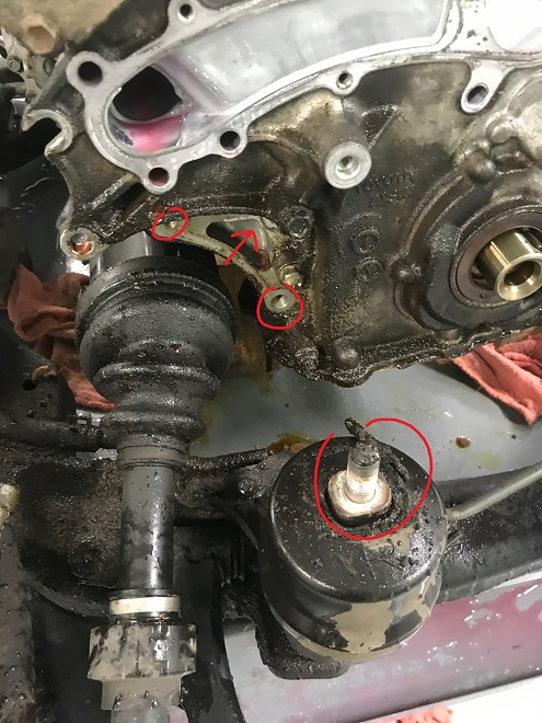
The R-134a is evacuated from the vehicle. The ports are indicated below by the red and blue fittings. Ground straps (circled) are removed. Any harness wires that connect the body to the drivetrain is to be removed and set aside. There may be others depending on the application.
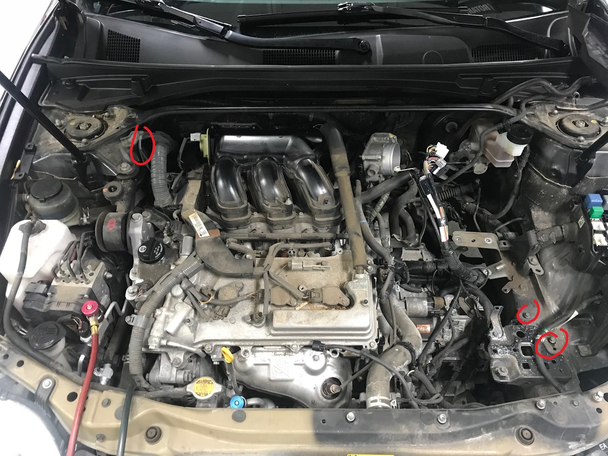
AC evacuation, ground straps
The above also shows how to position some of the harnesses and lines to minimize them catching on the chassis as it is raised off the drivetrain.
The ECM harness connector is removed. THIS METAL BRACKET IS SHARP!
ECU Disconnect Position
The ECU is disconnected by releasing the connector tab and pivoting the connector lever outward. If the lever is not fully released from the connector before pulling you risk breaking the securing tabs on the ECM or harness:
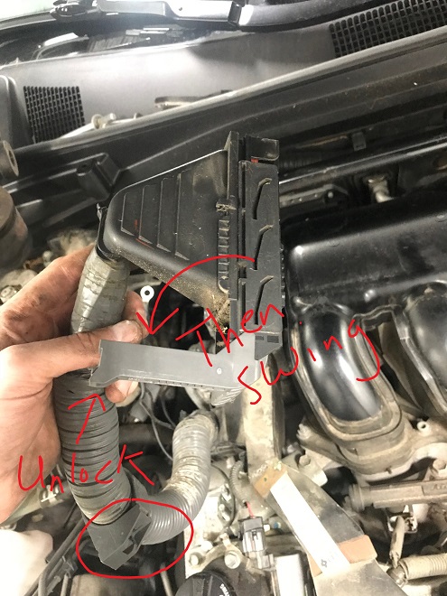
Disconnect ECU
Some 2GR-FE ECUs are in the cabin behind the glovebox. For these the glovebox requires removal to disconnect the ECU and other connectors, the harness being fed back through the firewall. Tape is put over all exposed connectors at the ECM and ECM harness. Anything that gets in there will ruin your day.
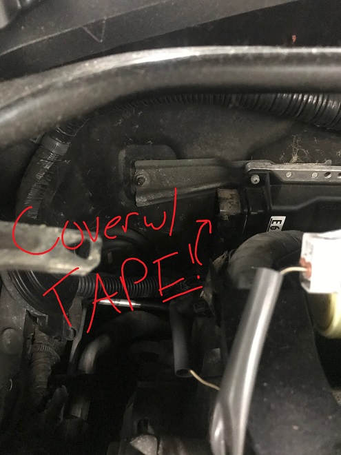
Cover The ECU
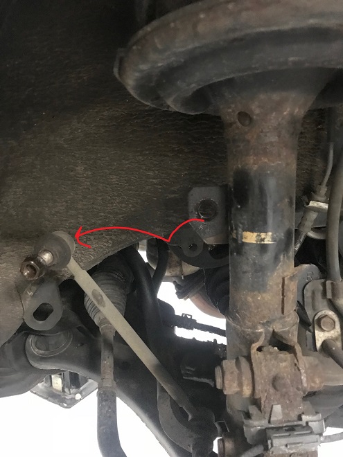
Moving on to the suspension (the following few steps need to be done for both front suspension assemblies):
Front Suspension Disconnect Guide
The front swaybar needs to be released from the strut and the axle from the hub/knuckle. Using a thread chaser on the swaybar endlink threads is a good first step for rusty threads:
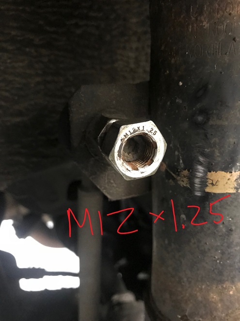
Chase Front Link Studs
The threads on the factory links on this ES350 are M12*1.25. With a strategic application of heat, a 17mm wrench and 6mm allen, the upper stud and nut is worked loose from both front struts. They are moved to the side:
Disconnected front links
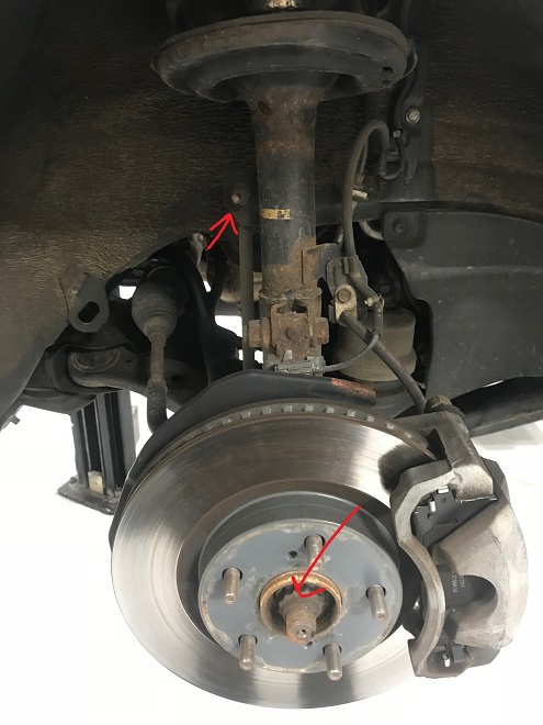
The front axle nut is unstaked:
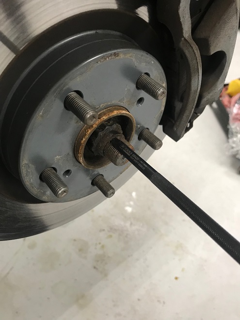
Unstake front axle nut
And removed. A 1/2″ impact is the best tool for this.

Remove front axle nut
The axle is driven in with an air hammer using the indent in the tip of the axle. Don’t hit the end of the axle with a hammer.
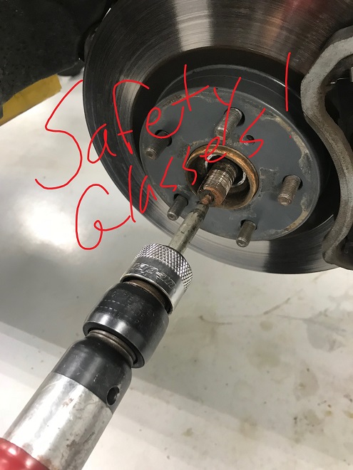
Push in front axle
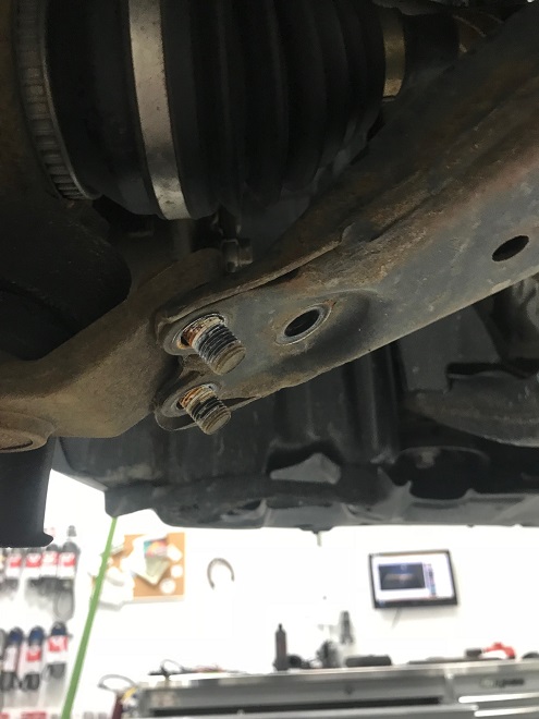
The lower ball joint is disconnected from the control arm. There are two nuts and one bolt per side:
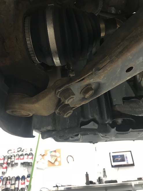
Control arm
Once removed the arm tilts:
Control arm released
And and can be separated with a pry bar:
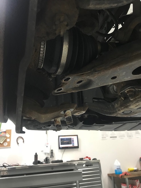
Control arm free
The ball join is swung free. The cotter pin is cut free on both outer tie rods and the tire rods nuts run off with an impact:
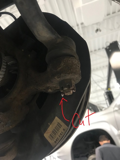
Tie rod cut cotter pin
With some strategic hammer hits the outer tie rod pops free of the knuckle. This extra play in the knuckle is used to pull the axle free of the hub and knuckle. The suspension is now disconnected.
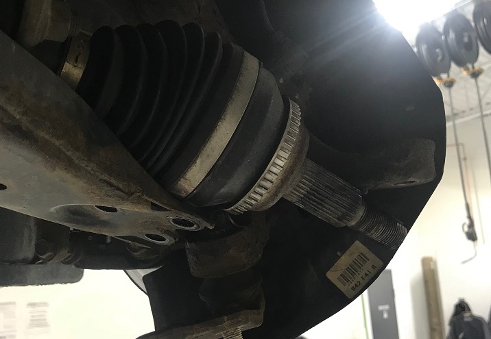
Removed axle
Both wheel wells have inner splash shields that need to be removed. Two bolts and one clip secure them each:
Removed splash shield, driver’s side
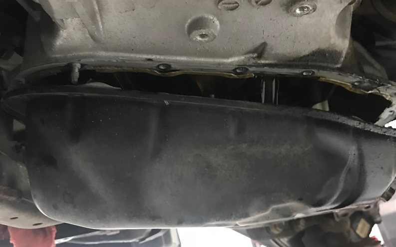
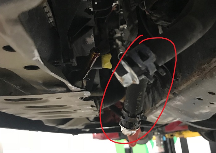
The next step is to drain fluids and remove the exhaust to gain access to the upper and lower oil pans (both which must be removed before dropping the drivetrain out). Here’s what we’re working with (note the lift arm locations aren’t too close to the rear subframe brackets, which is important later):
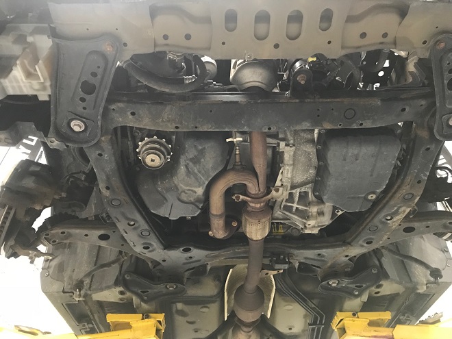
Under car view
The coolant is drained from the radiator:
Radiator drain, open with tube directing coolant
And the engine oil as well from the oil pan:
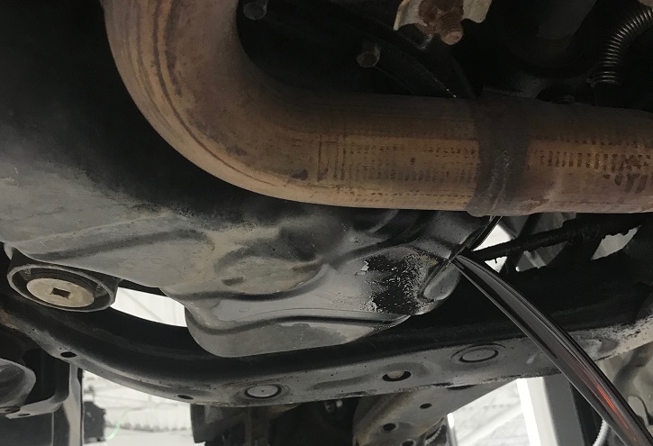
Draining the oil
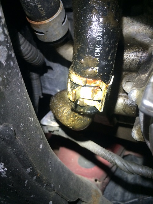
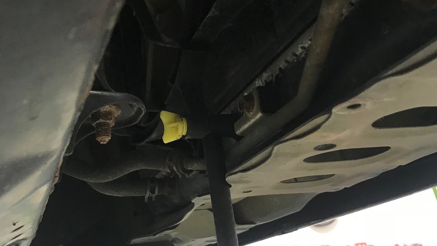
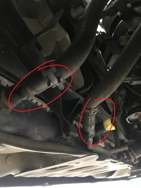
In the above you can see some of the oil buildup from the timing cover leak on the rear of the subframe. It was a big one. The front power steering soft line is disconnected from the hard line at the subframe (right front of the subframe near the A/C compressor). It’s a tight squeeze to get the hose off after releasing the clamp. The power steering reservoir will drain when this line is removed:
Front power steering line draining
The oxygen sensors are disconnected, located on top of the subframe near the front:
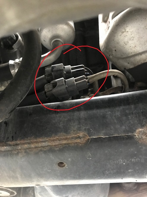
A/F sensor connectors
The fasteners for the exhaust that need to be removed:
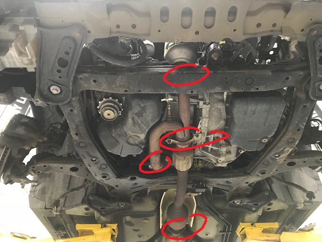
Exhaust fastener location
Two fasteners at the front bank, two at the rear bank, two at the back of the pipe, and two that secure the exhaust to the upper oil pan all must be removed. The rubber hanger may need to be removed as well, depending on how flexible the exhaust is (not pictured).
The hanger bracket that was above the exhaust and cover for the flex plate is removed:
Exhaust hanger bracket upper
And removed:
Exhaust hanger bracket removed
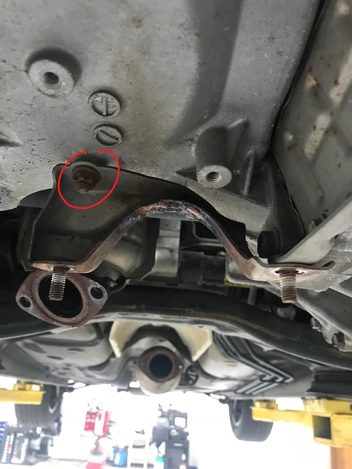
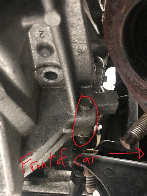
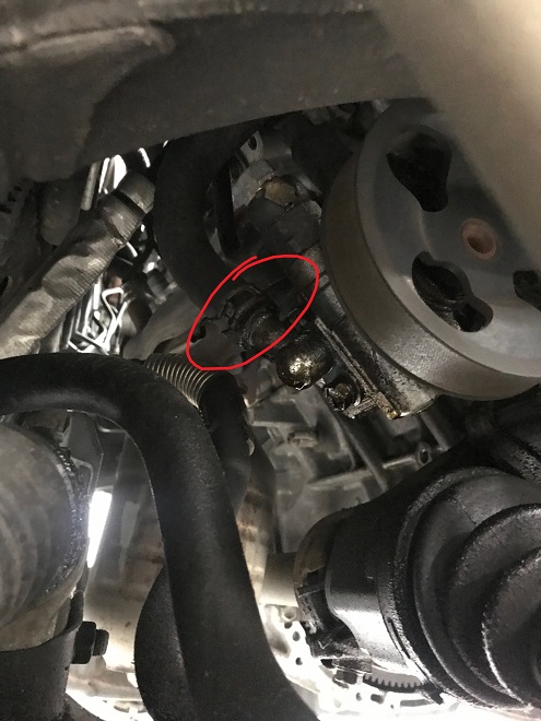
The lower oil pan removed by pulling all the 10mm fasteners. There is a hidden 10mm nut on a stud above the subframe. This one requires some tool creativity.
Removing lower oil pan fasteners and this hard to get nut
Once the lower oil pan bolts and nuts are out, a seal cutter tool is used to break the epoxy seal at this pry location. Go easy! Rushing here results in a destroyed lower or upper oil pan:
Lower oil pan pry location
The pan is loosened until the epoxy begins to release all around:
Lower oil pan partial removal
The oil pickup tube is removed, preparing to remove the upper oil pan:
Remove oil pickup tube, still connected
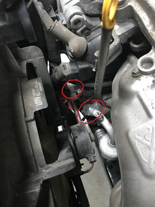
And the connector to the oil pressure sensor:
Oil pressure sensor connector
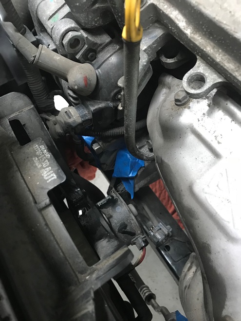
And the connector and harness securing tab for the oil level sensor:
Oil level connector removed out of the way
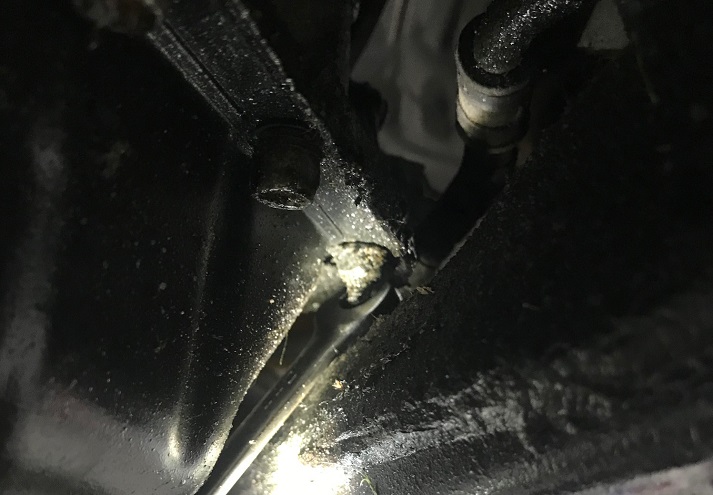
The oil level sensor does not need to be removed. Now it is time for the upper oil pan to be removed. There is a hidden large bolt that holds the transmission to the upper oil pan, threading in from the transmission side:
Hidden upper oil pan bolt
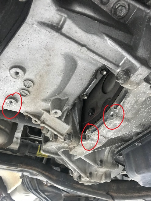
The rest are fairly easy to see, some inside the oil pan:
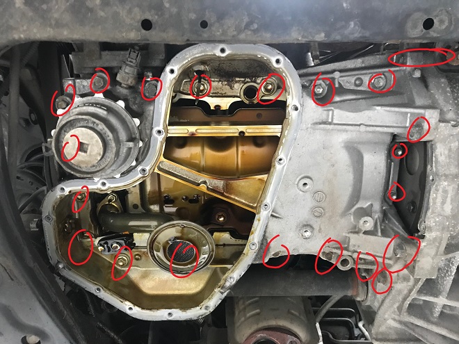
Upper oil pan bolt locations
The stud under the crank pulley must be removed. If you do not remove this stud the upper oil pan cannot clear the subframe easily. This is more important during installation, but do it now to make removal easier:
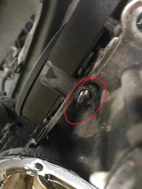
Remove this stud
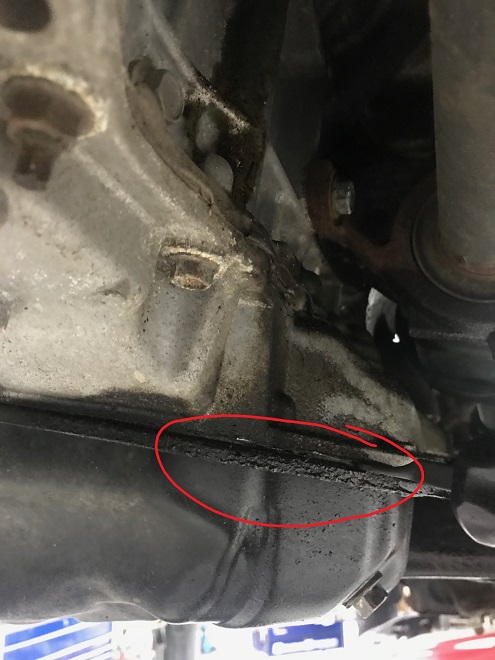
The upper oil pan has three pry locations. One on the front by the transmission:
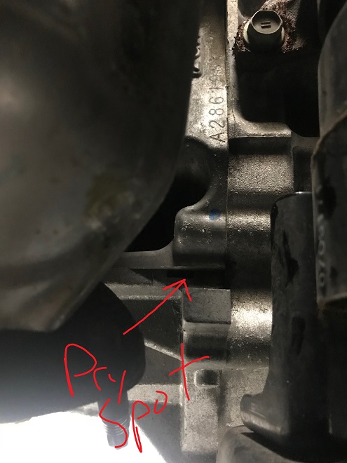
Front pry spot
On the back of the upper oil pan by the transmission:
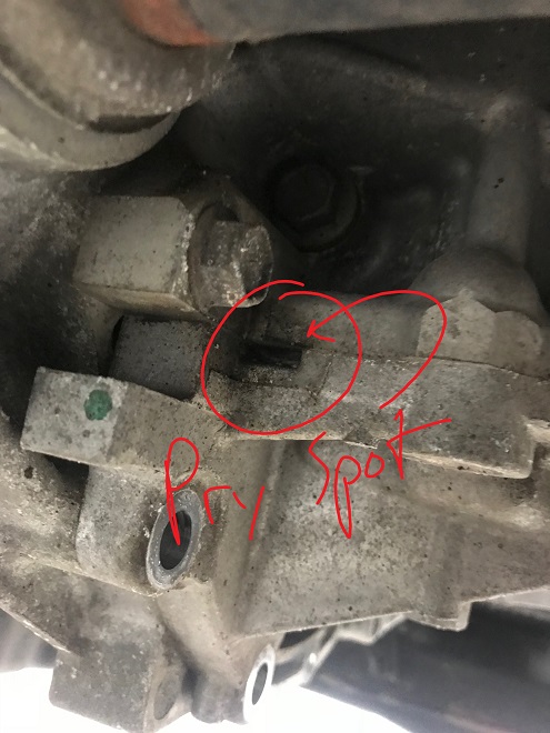
Rear pry spot
And up front by the crank pulley:
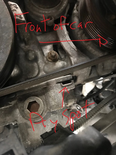
Pry spot by the crank pulley
Using those pry spots, pop the upper oil pan loose. If there is any unusual fight to get it loose, check to make sure no bolts are forgotten. There will be a slight fight at the dipstick o-ring, but it shouldn’t prevent the oil pan from popping loose. The 10mm bolts by the transmission are often forgotten. Once the upper oil pan is off, the o-rings for the oil filter/oil pump junction are removed:
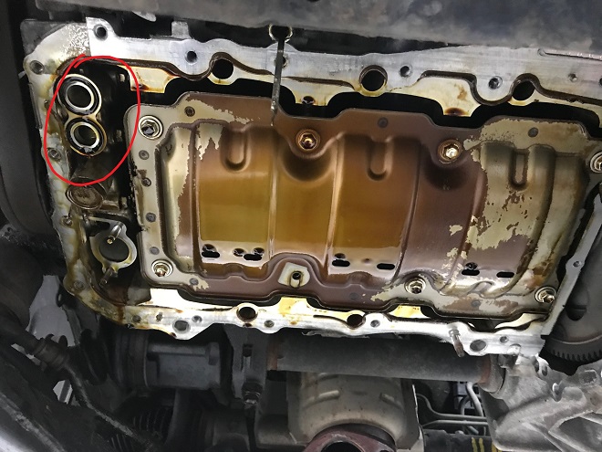
Upper oil pan off, oil pump o-rings before removal
Both transmission lines at the radiator are removed:
Transmission lines, unclamped but still in place
And plugged with some bolts to prevent dripping fluid out the transmission during the repairs:
Plugged transmission lines
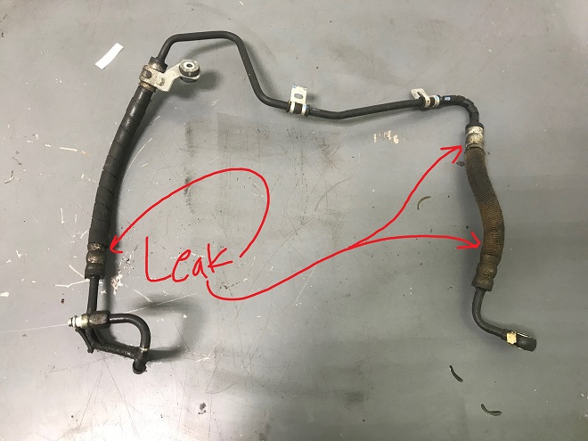
The power steering line at the pump is removed. This is very messy:
Power steering line at pump still secured
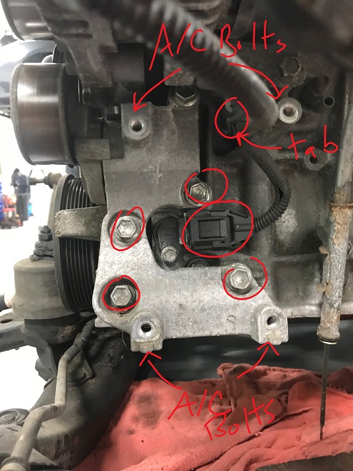
Moving back up top, both two 10mm bolts that secure the A/C lines to the compressor are removed. The dipstick is also unbolted from the cylinder head (not pictured):
Compressor bolt locations
The AC ports are taped over. Don’t want debris in the compressor!
Compressor ports taped
The lower radiator hose at the thermostat housing is disconnected. Why here? It’s easier than digging around at the base of the radiator:
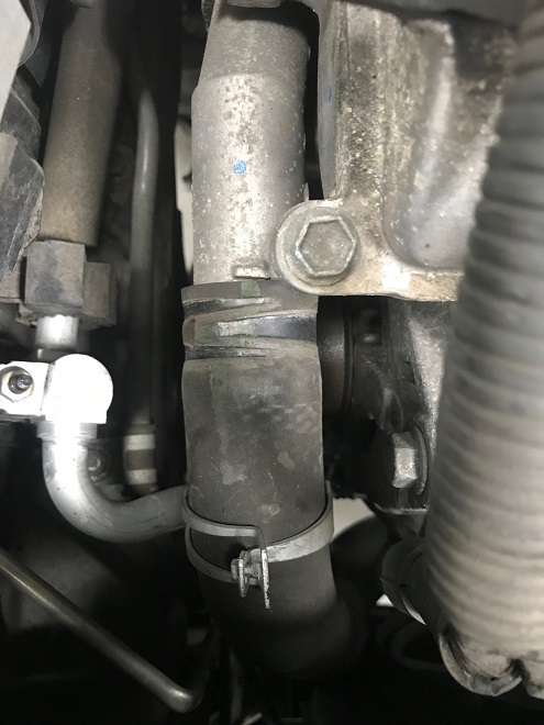
Lower radiator hose at thermostat housing, clamp removed
Tthe upper radiator hose at the engine side is also disconnected:
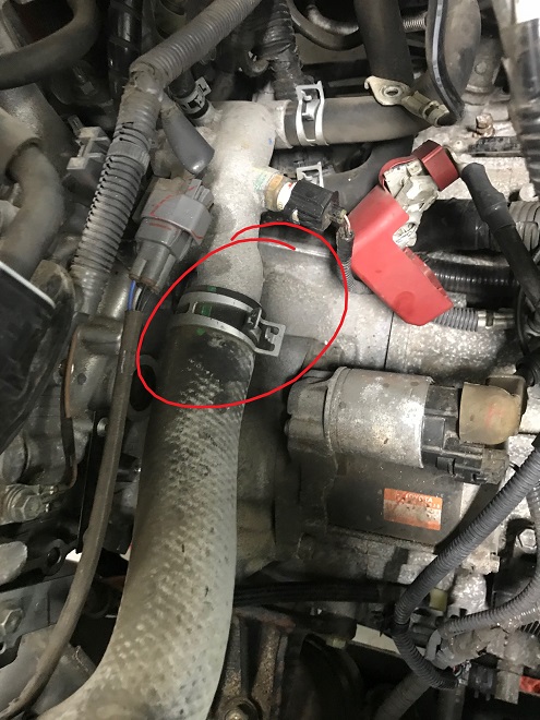
Upper radiator hose, still connected
Both the upper and lower heater core hoses are removed as well, labeling which hose goes on top:
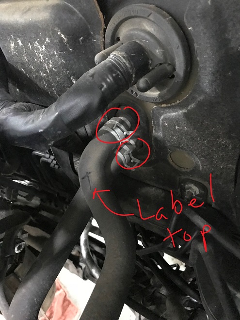
Heater core hoses, still connected
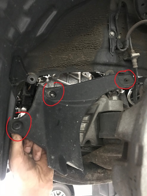
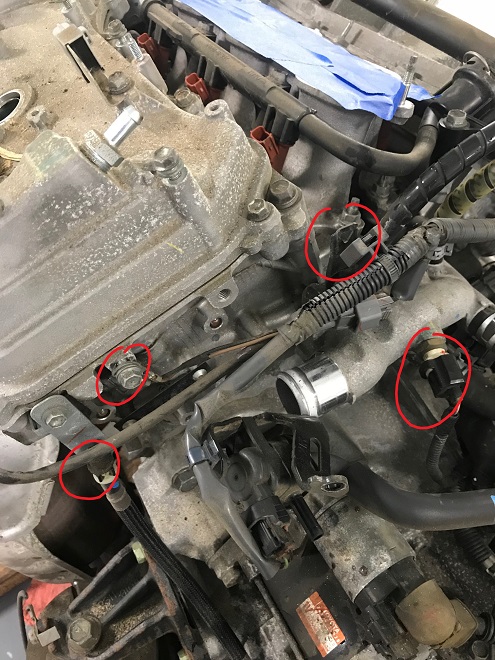
Time to remove the drivetrain from the vehicle. Removing the drivetrain is done by setting the subframe on a table and removing 4 main bolts and their securing brackets (reusing a picture from above):
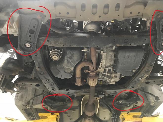
Subframe securing bolts and brackets
With the subframe securely resting on a rolling table that can support the weight of the vehicle, the brackets are unbolted first, then the main four bolts that hold the subframe to the vehicle. Slowly, inch by inch and while checking everything for clearance, the chassis is lifted free of the drivetrain.
Things that like to catch are the transmission shift cable, the lower radiator hose (it barely clear the A/C compressor), the A/C lines, and the power steering pump.
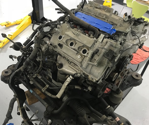
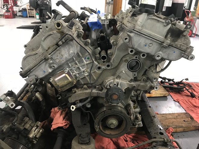
Here is the drivetrain removed:
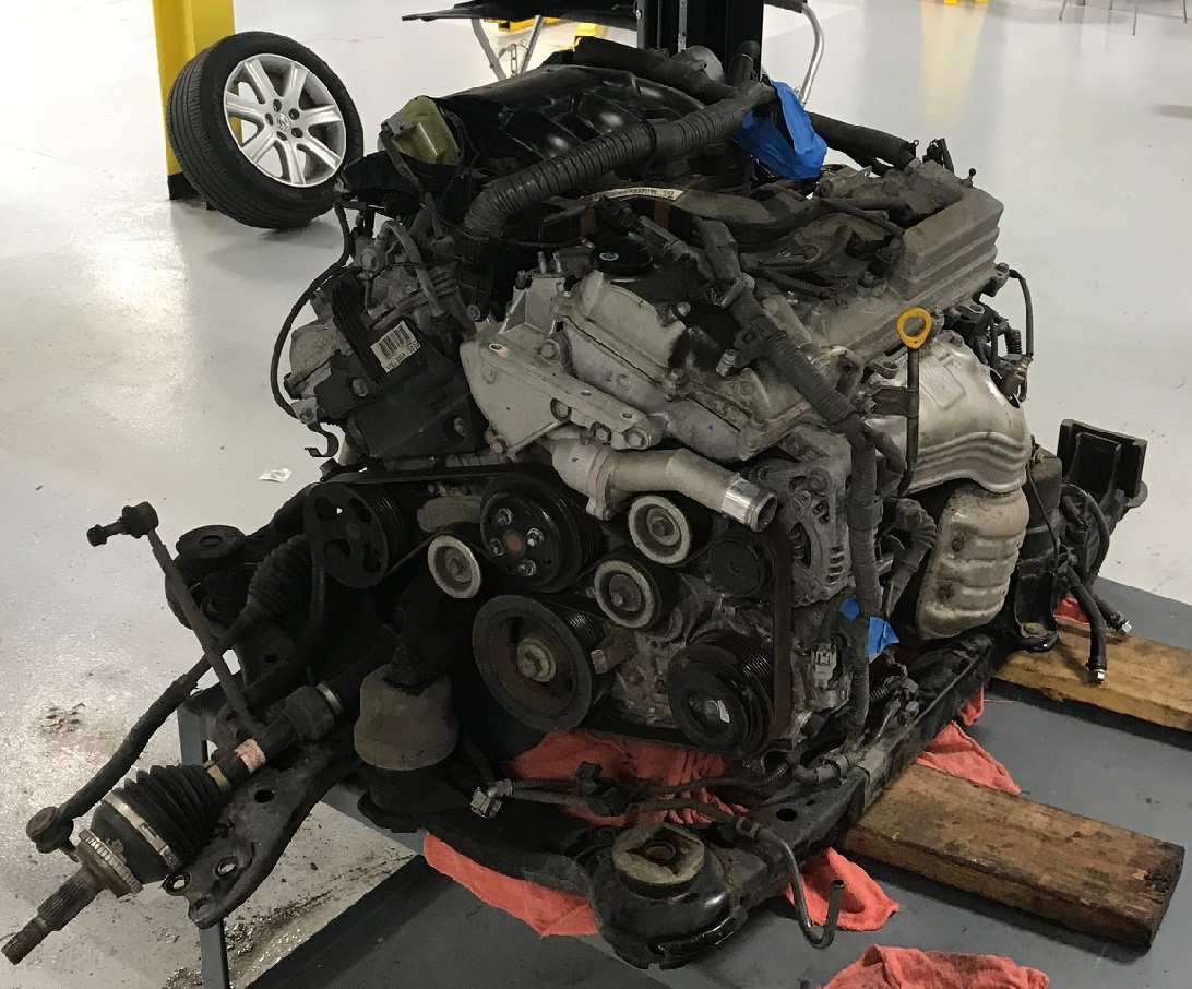
Engine out
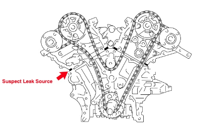
Here’s what you’re looking at on the front of the engine:
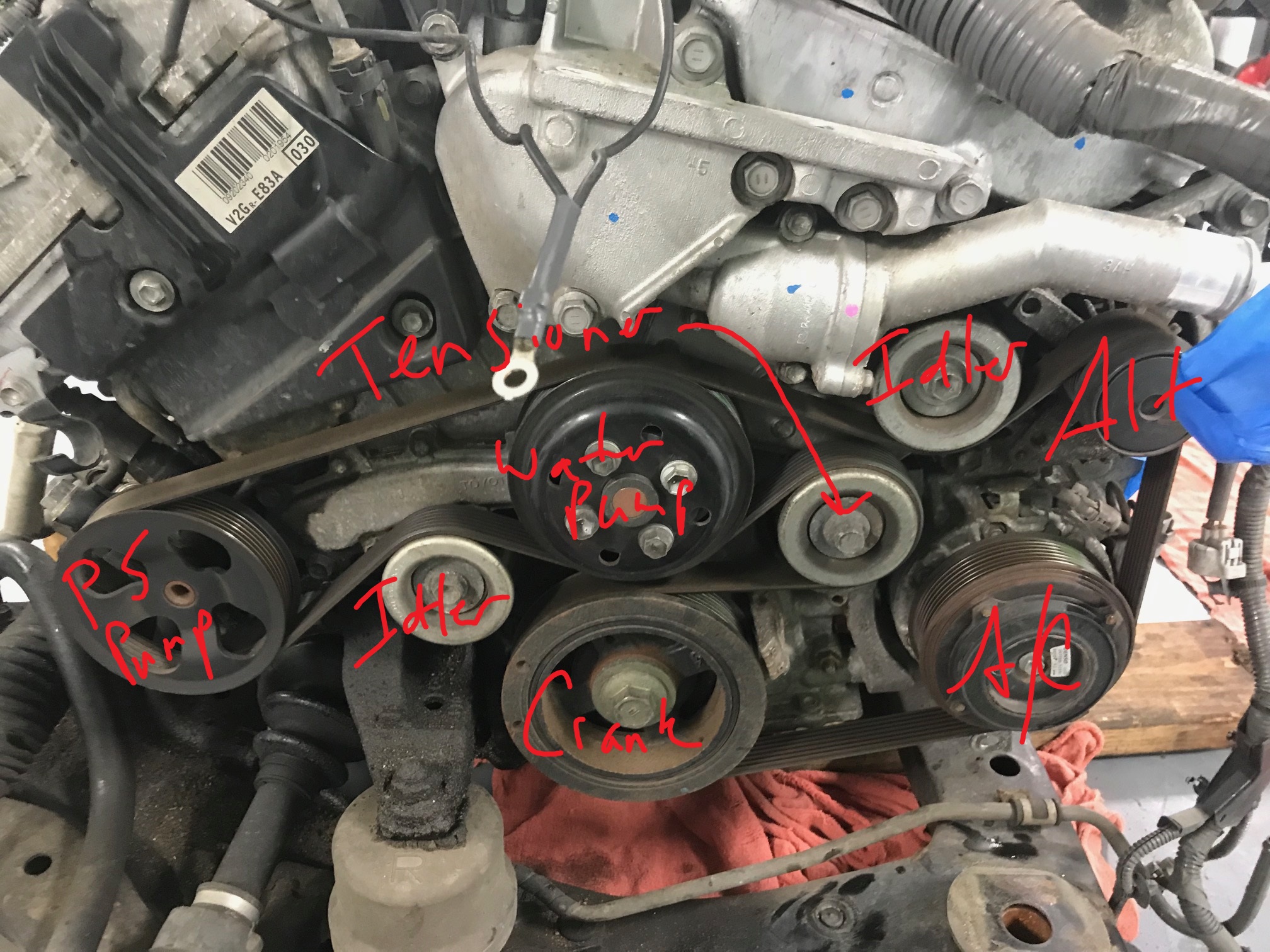
Engine front, labeled
The drive belt is removed. The tensioner is loosened by turning counter clockwise. This bolt on the tensioner pulley is reverse thread.

Remove drive belt
The connector at the A/C compressor and oxygen sensor connectors are disconnected and freed where they attach to the subframe:
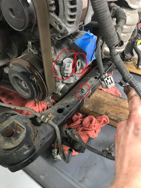
Disconnect the A/C compressor
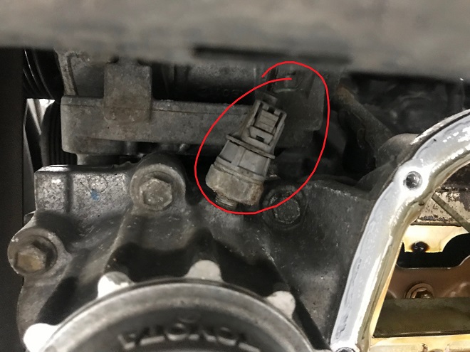
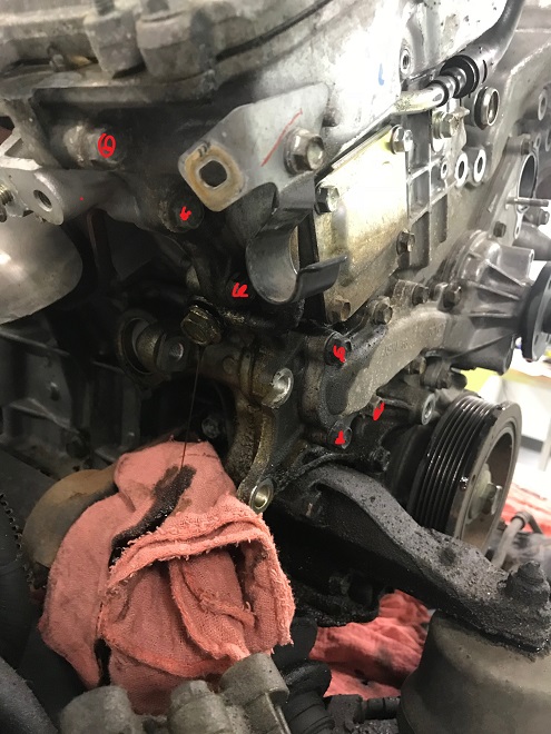
The A/C compressor is unbolted and set aside. This reveals the crank position sensor located behind the tensioner. The crank sensor is disconnected. The tensioner securing bolts are circled. It can be removed now or when the accessories are being removed (more later). There is also a harness tab that connects the harness to the alternator that needs to be released:
A/C compresor removed
Both coolant lines and connector at the throttle body are disconnected:
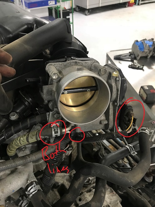
Throttle disconnect
While removing the three bolts that hold the upper intake plenum (two go into the plenum, one bolts a bracket to the valve cover), the A/F sensor, noise filter (lower left of picture), camshaft position sensor are disconnected, as well as the three rear ignition coils unbolted:
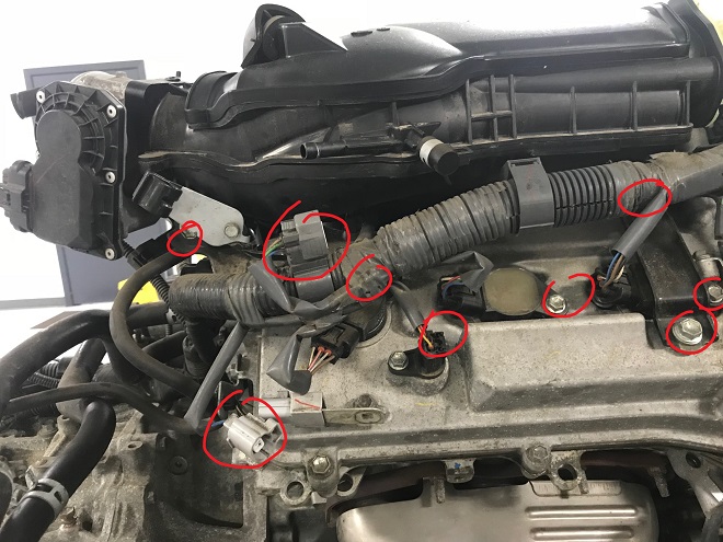
Back of plenum view
The 4 5mm Allen and 2 10mm nuts that bolt the plenum down are removed.
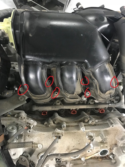
Plenum removal
Some of the fuel injectors and misc. other connectors have been disconnected in the above. We’ll get to that in a second. Here’s the plenum off:
Intake plenum off
The lower intake is taped over. You don’t want stuff going in there at this point. The next step is to peel the engine harness towards the rear of the engine and then over to the transmission, working methodically and carefully to not overstress any connectors or miss any harness clips or bolts. We strongly recommend the ignition coils remain connected to the harness. The connectors like to break. The technician broke a few on purpose to illustrate this:
I swear this was on purpose
Any Toyota dealer will have a dozen or so of these connectors in stock if they are broken. They are a simple 4-pin seal connector and cost less than $10 each but are a pain nevertheless. Leave the coils connected to avoid this. CARspec stocks these connectors for this reasons (and the connector seems to be the same for most 2002-2015 models, regardless if 4,6 or 8 cylinder).
The goal is to get the harness clear of the engine, like this:
Harness clear of engine
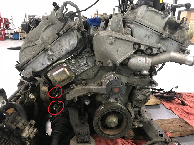
There are a few connectors on the transmission side of the engine that are removed as well:
Connectors and fasteners transmission side
The tensioner and idler pullies for the drive belt are removed, noting that the tensioner pulley is reverse thread:
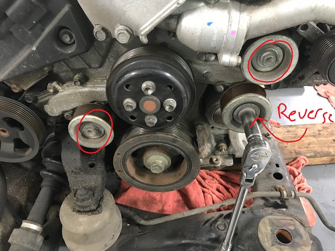
Remove three pullies
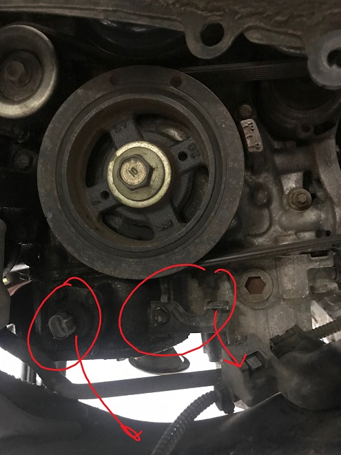
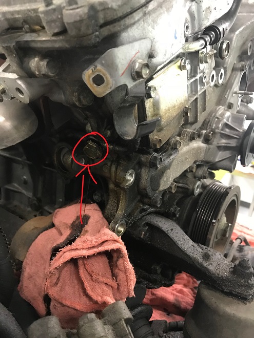
And the alternator, for which there are two fasteners that secure it to the timing cover and one hidden fastener to the block. The water pump pulley is removed as well.
Alternator bolt spots
And the hidden one (arrow) for the alternator. The tensioner is removed:

Hidden bolt and removing the tensioner
And the Bank 1 VVT oil feed line cover via two bolts.
Remove these to remove the cover
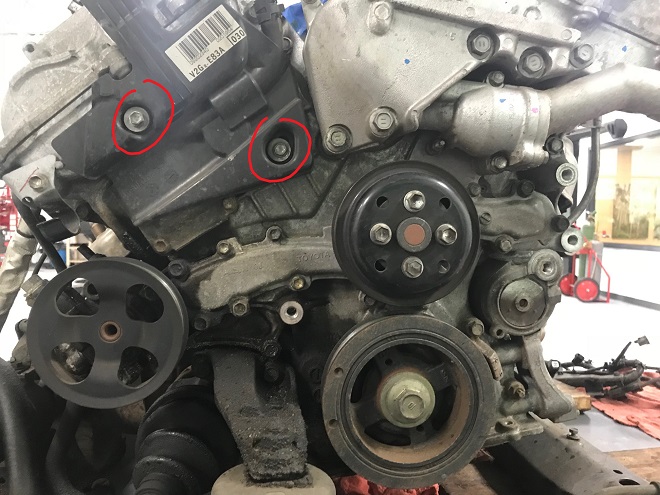
Now the power steering pump. The two securing bolts for the pump are access through the pulley:
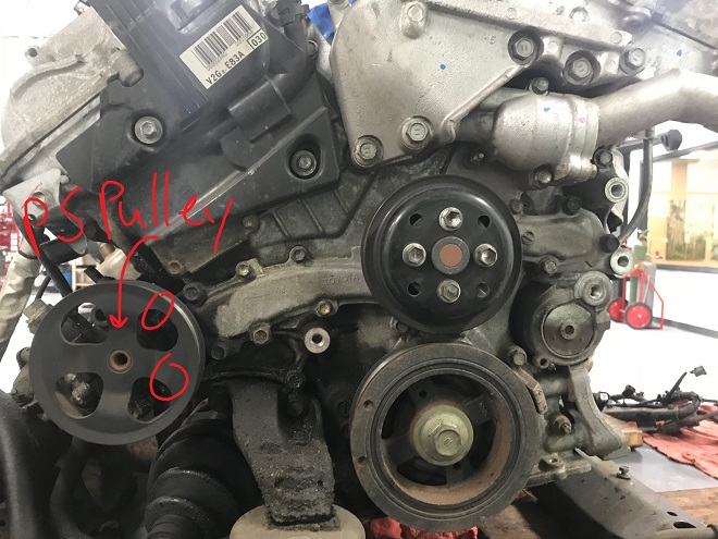
Power steering installed
And removed:
Power steering removed
Next the engine mount:
Mount removal bolts
And the thermostat housing(three fasteners):
Thermostat housing removal
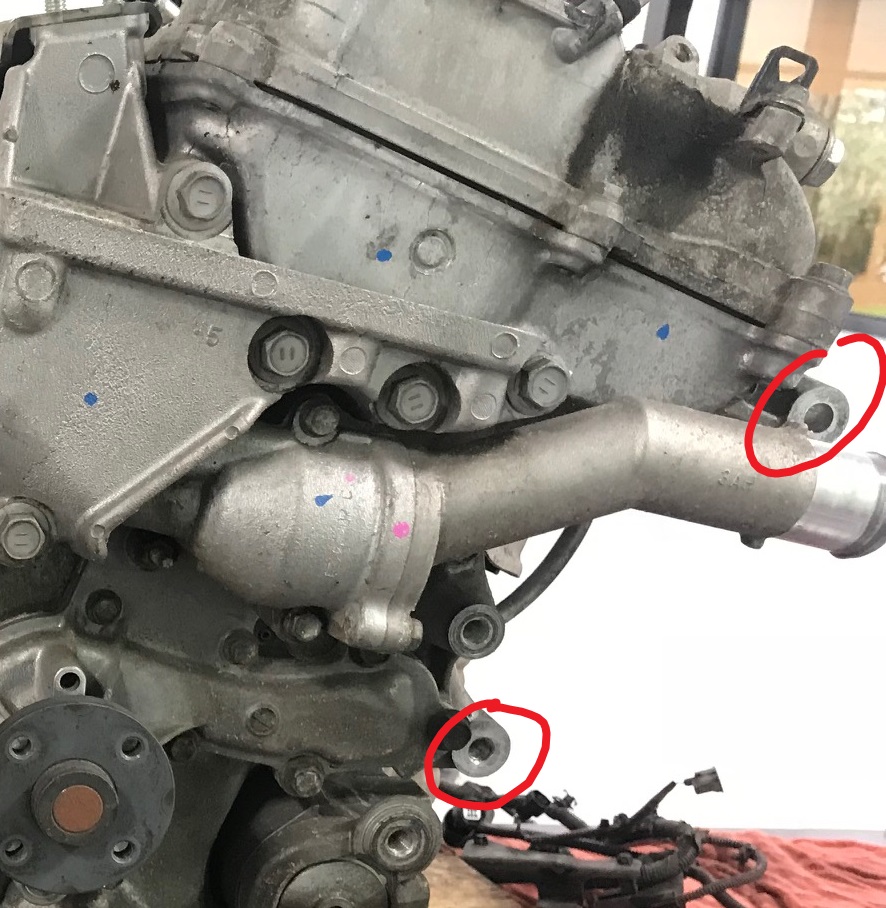
The 10mm bolt and upper VVT feed banjo fitting for Bank 1 are now removed:
VVT Bank 1 Feed Line
Then the lower, hidden banjo fitting (behind where the power steering pump was). This barfs oil:
Bank 1 VVT lower banjo fitting
And the same with the bank 2 VVT oil feed line:
Bank 2 VVT feed line removed
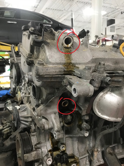
MAKE SURE YOU RECOVER THE SMALL SCREENS THAT GO INTO EACH UPPER BANJO FITTING AT THE VALVE COVER (not pictured). These need to be cleaned and checked for debris!
Here’s where this engine is now:
Engine before valve cover removal
Note these two . They need to be replaced before reassembly. More on the smaller one later:

Thermostat housing o-rings
Now we’re ready to remove the valve covers. Both are heald on by roughly a dozen 10mm/12mm bolts. Keep them organized as their length and location matter. Once you have pulled all the fasteners, there are specific pry locations next to locating dowels to help prevent breaking the aluminum covers. You’ll want to carefully pry next to the tabs with dowels on them, seen here on Bank 1 on the back corner:

Bank 1 dowel pry spot
And on Bank 2:
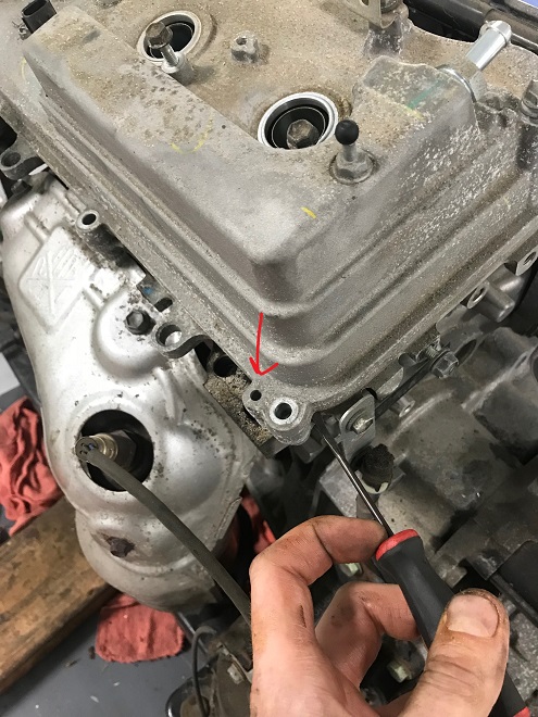
Bank 2 dowel pry spot
There are other dowels closer to the timing cover, however CARspec has found prying near to the pictured dowels minimizes the likelihood of breaking the covers. The steel dowels can seized to the aluminum covers, so use penetrating spray and gentle wiggling as needed. If one of these tabs is broken off the valve cover gasket will not seat properly at the corners, resulting in a leak.
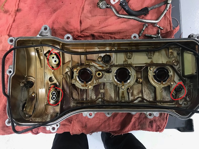
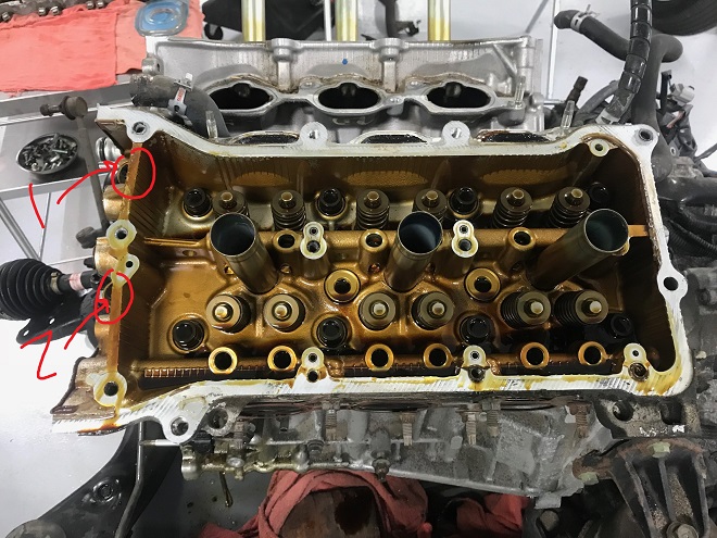
Once the covers are off, inspect the VVT oil feed ports and camshaft lubrication port for stuck o-rings. Here’s the inside of bank 1, highlighting where the o-rings may be. Two are stuck to the inside of cover:
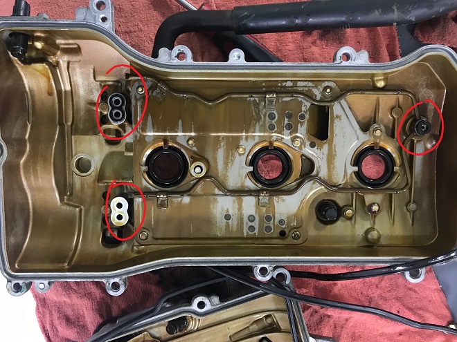
Bank 1 inside
And on the engine side of bank 1, one is stuck in the VVT oil galley seat:
Bank 1 stuck o-ring
Same thing for bank 2:
Bank 2 cover inside
And on the engine side:
Bank 2 stuck o-ring
Failure to recover the o-rings, forgetting to install new ones, or doubling up on them will result in low oil pressure, VVT malfunction and potential engine damage. These little dudes are tricky.
Out comes the bank 1 exhaust manifold:
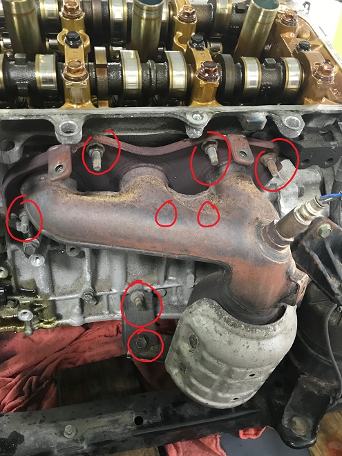
Bank 2 manifold
And removed:
Bank 2 manifold removed
And for the other side as well:
Bank 1 removed
Next out is the transmission side crossover pipe that links the heads to the center crossover pipe, which has three fasteners on each head and an o-ring in the middle:
Crossover pipe view from top
And removed:
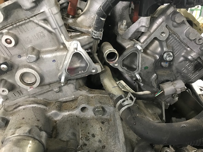
Crossover pipe removed
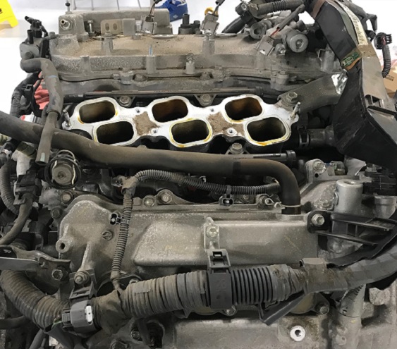
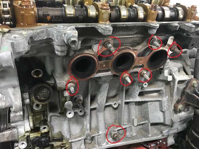
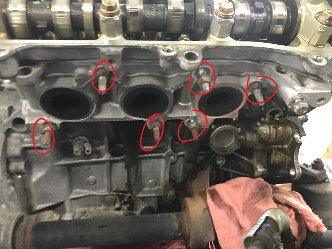
Next the lower intake, fuel injectors, and fuel rail all come out as one unit. Here’s the lower intake removed exposing the fastener location and the engine valley:
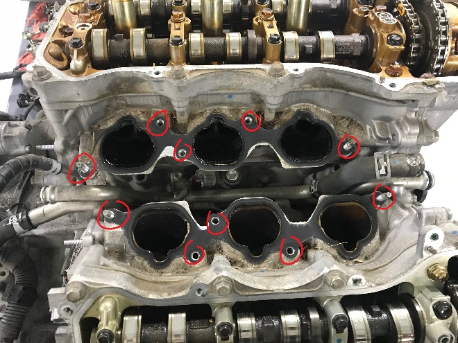
Lower intake removed
Set the lower intake upside down so as to not damage the injectors. They stick out the bottom of the manifold:
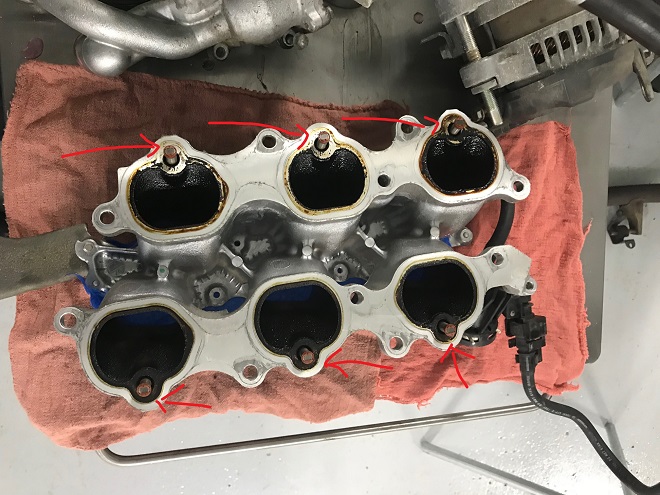
Lower intake off
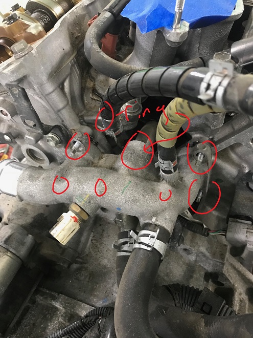
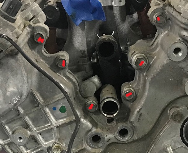
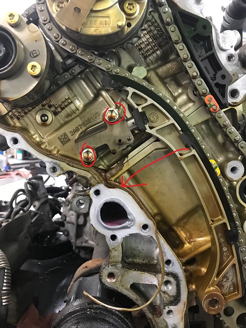
Looking back at the valley of the engine, note the two places where the o-rings go (left, rear o-ring was removed already). These need to be replaced upon reassembly, and roll/pinch easily if not carefully reassembled! The o-ring on the right side of the picture goes into the thermostat housing.
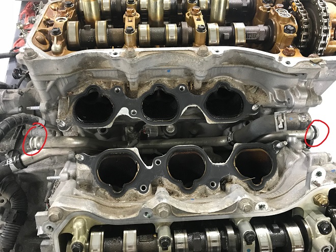
Crossover pipe o-rings
At this point some creativity is required, as the front lower engine mount must be removed to allow the timing cover to be removed. The mount block access to a few of the bolts and a but that secure the timing cover.
In order to remove the mount, the engine is supported (in this case with a piece of wood supporting the edge of the short block):
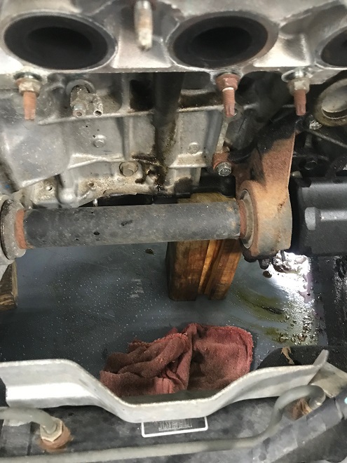
Sometimes it just take a piece of 4*4
And the mount can be removed:
Front mount removed
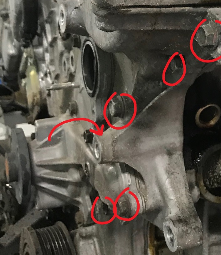
The next step is technician’s choice: you can remove the water pump from the timing cover before removing the timing cover, or remove the timing cover with the water pump still attached. A few of the larger bolts that hold the water pump on also secure the timing cover, so most CARspec technicians pull the water pump before the timing cover. Here are the fasteners for the water pump:
Water pump removal
Beware, you’re gonna have coolant barf out the front. The crank pulley is then removed (not pictured). A 1/2″ or 3/4″ impact is the best bet for the crank main bolt.
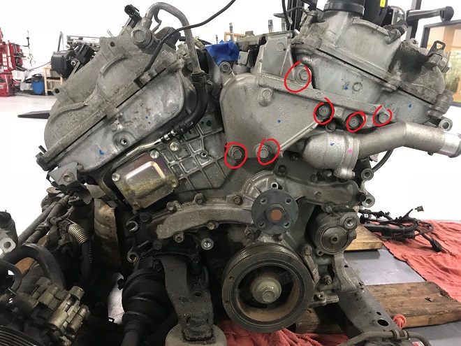
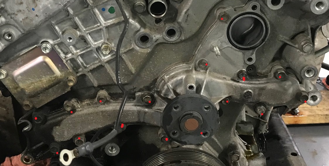
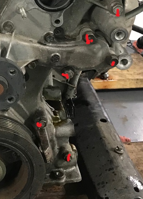
The timing cover is secured with 23 bolts and 2 nuts. Some of the bolts that secure the water pump also secure the timing cover (hence the tech’s choice of when to pull the pump). Some of these photos are out of order in disassembly.
Starting in the upper left:
Upper left bolts
In the valley of the engine:
Valley bolts
On the upper right of the cover:
Upper right bolts
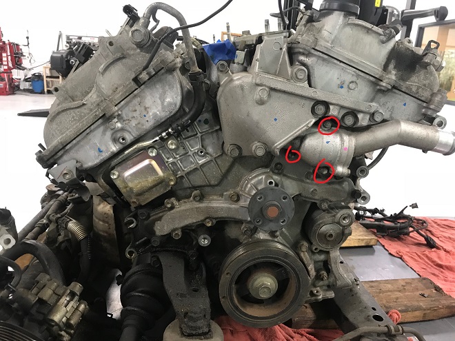
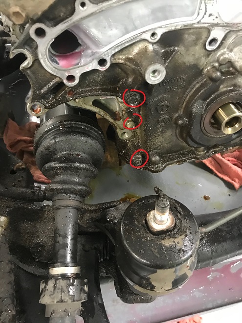
The lower right, with some overlap with the upper right with a better view:
Lower right bolts
The lower left:
Lower left bolts
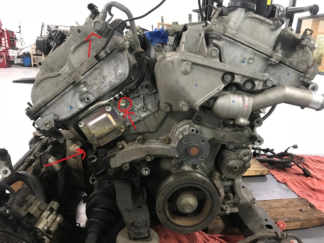
Two central bolts that run through the water pump:
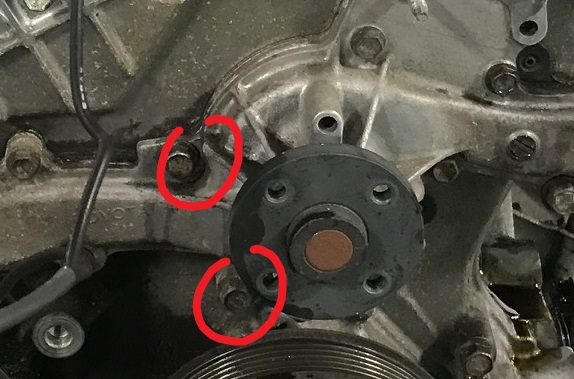
Water pump center timing cover bolts
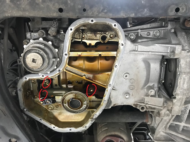
Pry carefully and evenly on the timing cover to break the epoxy seal. There are no set pry point (unlike the upper oil pan), so get creative. Here’s what you’ll be looking at with the cover off:
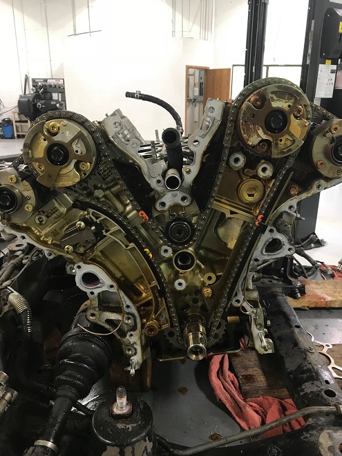
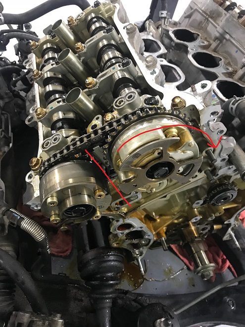
Timing cover off
In the above, the primary timing chain runs both intake variable valve timing (VVT) gears off of the crank sprocket. Two secondary chains run the exhaust VVT gears off of the intake VVT gears.
Set the engine to TDC, with the crank sprocket dot lining up with a casting mark in the block:
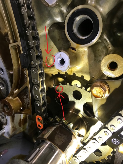
Crank set to TDC
This is where things get weird. All of the timing marks across the VVT gears and crank do not perfectly line up. Close, but not perfect.
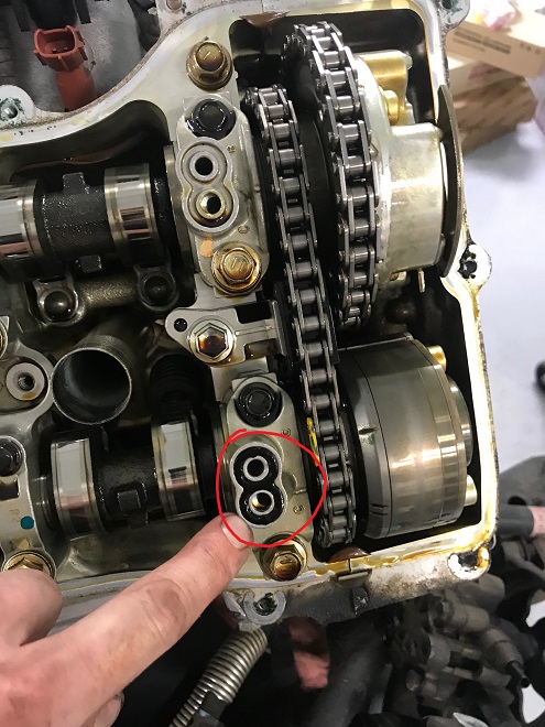
Line up the Bank 1 gears as seen here:
Bank 1 set to TDC
The bank 1 intake VVT gear single notch between the house shaped notch and another single notch should line up with the notch on the cam cap. The bank 1 exhaust VVT gear single notch just behind the flat spot on the VVT gear’s exterior should line up with the notch on the cam cap.
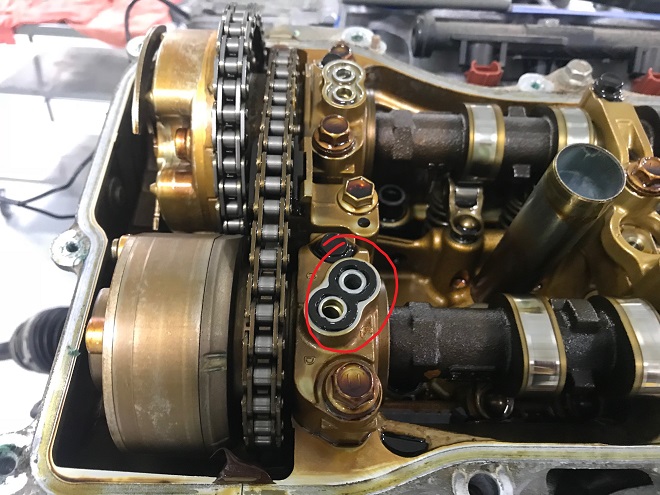
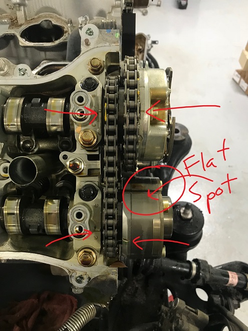
And Bank 2:
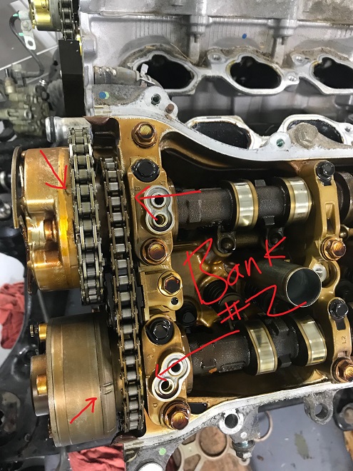
Bank 2 set to TDC
The house shape on the bank 2 intake VVT gear should roughly line up with the notch on cam cap. The double notch on the bank 2 exhaust VVT gear should roughly line up with the notch on the cam cap.
The primary chain tensioner is removed as well as the guide swung away to allow for chain slack:
Removing the tensioner, guide
With the primary chain now loose, the bank 1 intake VVT is rotated clock wise roughly 40 degrees to align the flat spot of the bank 1 exhaust camshaft perpendicular to the top of the engine. The bank 1 intake cam is under tension from the valve springs. It wants to jump in your hand so be ready:
Turning the VVT gear
This allows for enough slack to remove the primary chain and all the guides. Below the bank 2 valley chain guide is pulled from its dowels and the long guide unbolted (circled):
Bank 2 view with no chain, guides
With the primary chain removed, both bank 1 VVT gears can be removed at the same time. Both VVT gear bolts are removed (seen loosened below, also highlighting the removed chain guide from its dowels):
Bank 1 bolts removed, guide off
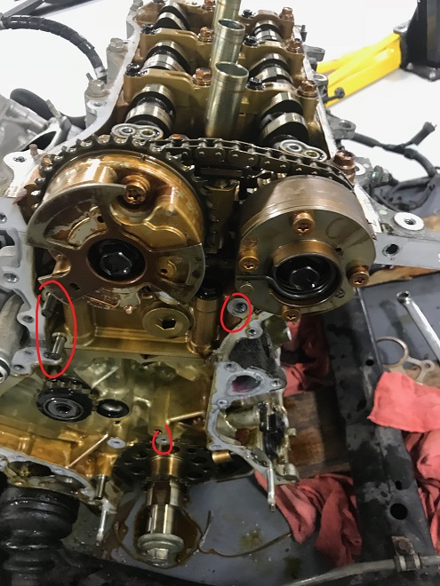
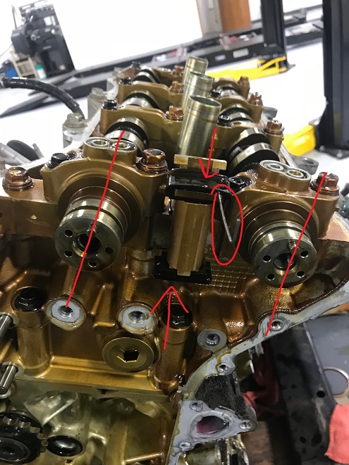
The VVT gears are removed as a pair. The bank 1 secondary chain tensioner is compressed on both sides and held by a pin (circled). Note the camshaft locating dowel angles. It is vital these be in this position before removing the camshafts in later steps. Failure to do so may cause the camshafts, cam caps, or cam carriers to fail during removal due to unusual tension from the valve springs. The secondary tensioner is unbolted (not pictured):
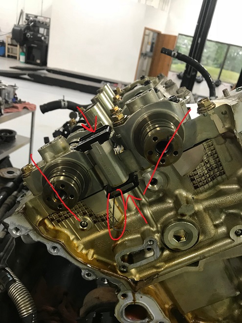
Bank 1 bare cams
Here’s looking into the bank 1 valve assembly at this stage:
Bank 1 bare cams
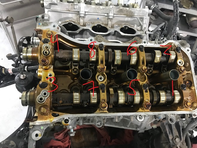
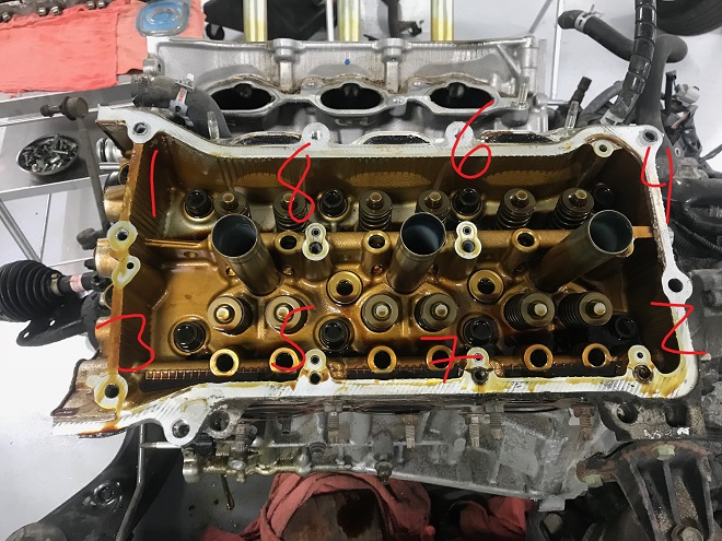
Removal of the 10mm smaller cam cap bolts is in a specific order to slowly release tension on the cams from the valve springs, and should be performed over many passes. If you run the bolts out one at a time, even in the right order, you risk snapping a cam or cam cap off. This is very expensive mistake. Remove in this order:

Bank 1 small bolt removal
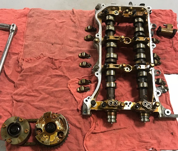
And then the larger bolts. The cams like to fall out due to the angle of the head so look out!
Bank 1 cam carrier removal
With the cam caps removed as seen below. Note that the cam carriers are also loose but are secured with the sealing expoxy and a few bolts left partially threaded to prevent them popping out unexpectedly:
Bank 1 cams only in the carrier. Beware, it’s easy to knock a camshaft out.
With the cams out:
Bank 1 cams out
Collect the 12 roller-followers (now just held in place with gravity) and 12 lifters. Immediately submerge the lifters in an oil bath to minimize air getting in them as the oil leaks out. More on that later. With all the cam carrier bolts removed the cam carrier can be removed after breaking the epoxy seal, revealing the bare head:
Bank 1 bare head
Organization is key at this point:
Bank 1 organized
Removed by several passes of the head bolts in a specific order as seen below:
Bank 1 head bolt removal order
The head can be set aside after being pulled off the locating dowels in the block.
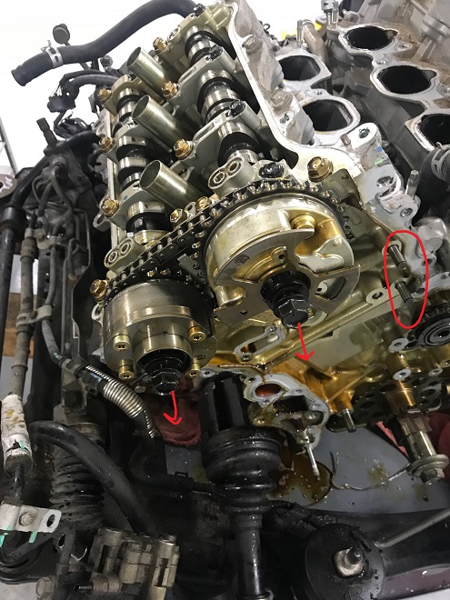
Bank 2 is a similar procedure: the bank 2 VVT gears and secondary timing chain are removed as one piece by loosening both VVT gear securing bolts and set aside. The secondary tensioner is compressed and set with a pin (circled), then removed (removal not pictured). Note the orientation of the camshaft dowels. Like on bank 1, these must be as pictured to prevent damage during further steps (and they should be in this position if you set the engine to TDC correctly). The intake cam should be slightly tilted in the direction of the exhaust cam, the exhaust cam almost vertical:
Bank 2 bare cams, set tensioner
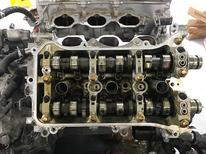
The bank 2 view now:

Bank 2 before cap removal
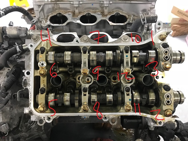
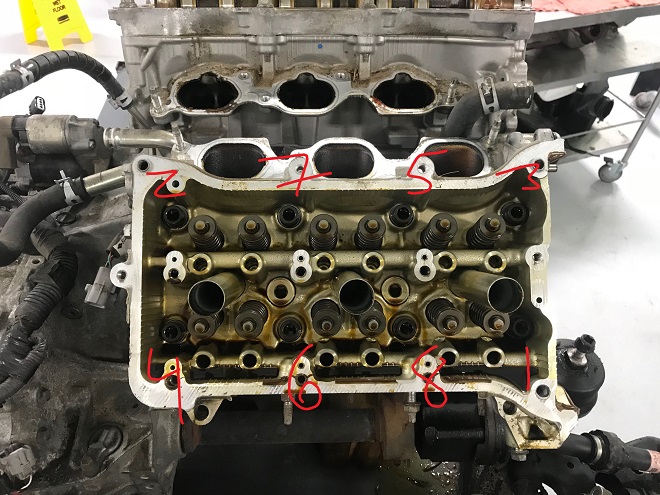
The 10mm cam cap bolts are removed in many passes:
Bank 2 small bolt removal order
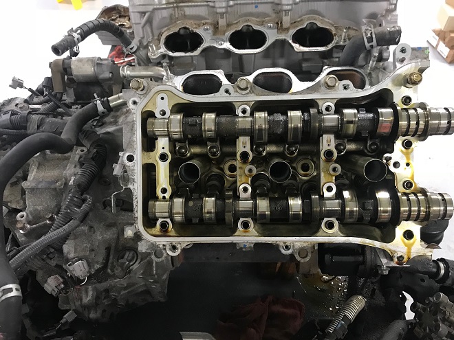
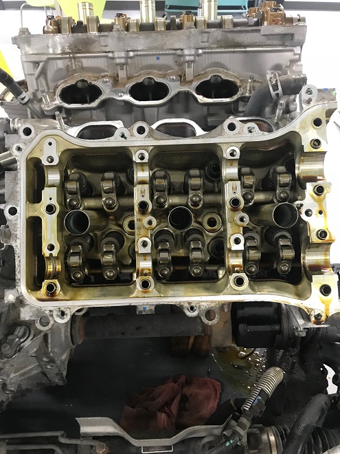
And the larger cam cap and carrier bolts in many passes. Stuff ( cams, cam caps) likes to fall out at this point so heads up:

Bank 2 cam cap and carrier removal
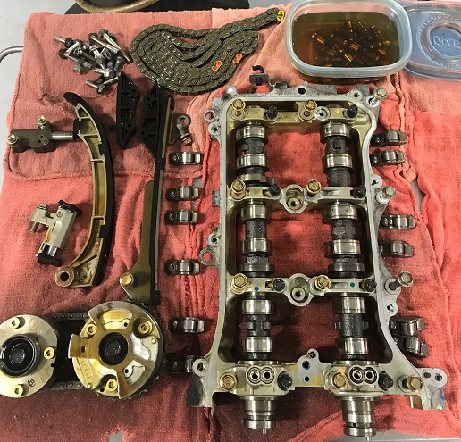
With the camshafts and cam carriers removed in the same fashion as bank 1, the roller-followers and lifters are removed and the lifters placed in an oil bath. Organization is key:
Bank 2 organized
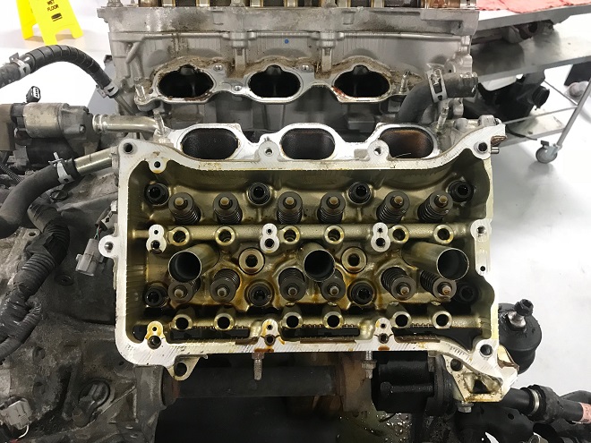
Bank 2 has an addition pair of smaller head bolts that must be removed first:
Bank 2 first head studs
With the head studs removed in several passes in a specific order a la Bank 1:
Bank 2 head stud removal
With the block deck now open, the deck needs to be inspected for old head gasket material or corrosion. Here are some spots that needed cleaning on bank 1:
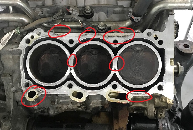
Block deck in need of cleaning
The goal is to make a surface free of any irregularity you can feel. The appearance doesn’t matter as much as the smoothness. Some places may look suspect but are generally OK if they feel perfectly smooth:
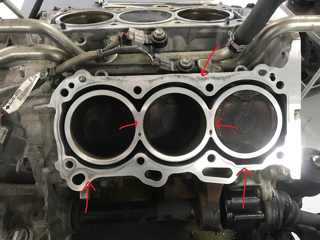
Bank 1 cleaned up
Teardown of the head is similar, with the removal of the valve springs and retainers with any spring compression tool. The head also needs to be inspected and cleaned like the block:
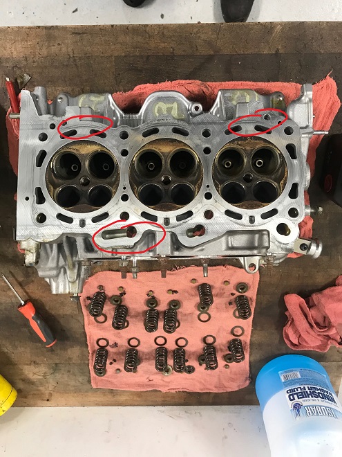
Bank 1 head disassembled
At this point, teardown is complete. The majority of reassembly is cleaning of old gasket material, removal of epoxy and reassembly in the reverse of teardown.
As Minneapolis, Minnesota’s premier independent Toyota and Lexus specialist we hope you enjoyed this long blog!